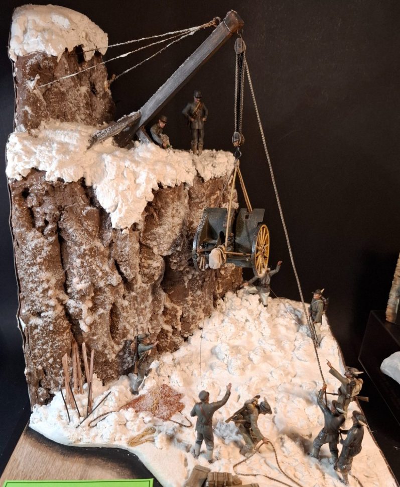
Italian 75mm Cannon and Crew in an Alpine setting
1/35th scale 3D printed kit from Art Station
Assembled and painted in 2025
I’ll begin by saying that this is a brilliant kit, based on drawings and pictures from the early 1900’s and I think it was a fantastic and daring company that chose to produce and offer this production.
HOLD the above comment in your memory, because I stand by that completely.
But a little knowledge is a dangerous thing, and whilst the components are all you’ll need to make a very nice diorama, there are a few things wrong.
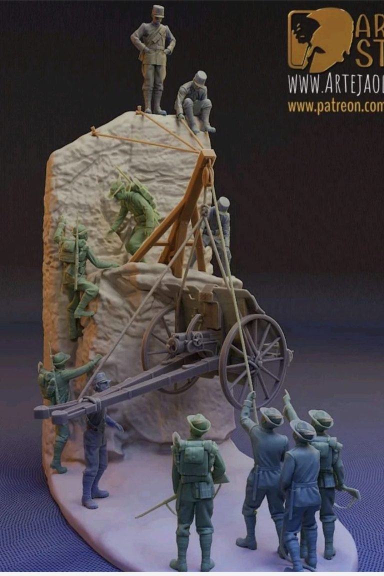
For my part, having worked on a seaside port for several years, alongside a functioning crane, and having gained level four Rigger and Banksman training – which means I was in a position to mentor people new to working around crane lift operations, I look at the box art in photo #1 and wonder several things.
First of all….
If the gun is being lowered to the ground, where has it come from, because there is no pick-up spot for the crane to have lifted it from, and if it’s being lifted up to a higher level, then there’s nowhere that the crane can land it..
The crane is a fixed jib, so it cannot extend, nor can it traverse.
That’s all a problem, because it means that the suspended gun is not really going anywhere.
The next problem….
That’s a single pulley block on the jib, one rope going over a moving wheel within the block.
This type of gun – a Cannone da 75/27 Modello 11 weighs around 1015kg. It’s not excessively heavy for a 75mm gun I grant you, but with that single wheel pulley block, two men are not going to be able to hold it in place, let alone lift it.
I’m working on Italian men of the time, like all Europeans in the first two decades of the 20th century, being slightly smaller, although on average more used to manual work, than nowadays. Lets say they weigh in at about 70kg each.
That means that to counterbalance the gun on that single wheel pulley block, with estimated friction, it would probably take fourteen of them just to hold it in place..
To lift it, lets say sixteen of them working very hard and in synchronisation so as not to let it fall.
The two figures holding the rope in this model are going to be dangling from the rope completely free of any contact with the ground.
So we need to calculate how this gun could be lifted by a reasonably small number of men.
Calculations for such things are available online – just Google “Block and Tackle Lift Calculator”, but more of that later.
Excuses for the kit producer.
I’ll remind you that I genuinely think this is a great kit, it’s a fair leap of faith for a company to produce something this complex and with so many components, and I congratulate them on it – Again, I do mean this, and I’m not trying to put you off buying it. It just needs a couple of simple adjustments if you want to be completely accurate.
Let’s look at the kit parts then, just so you know what you get, and how it’s delivered.
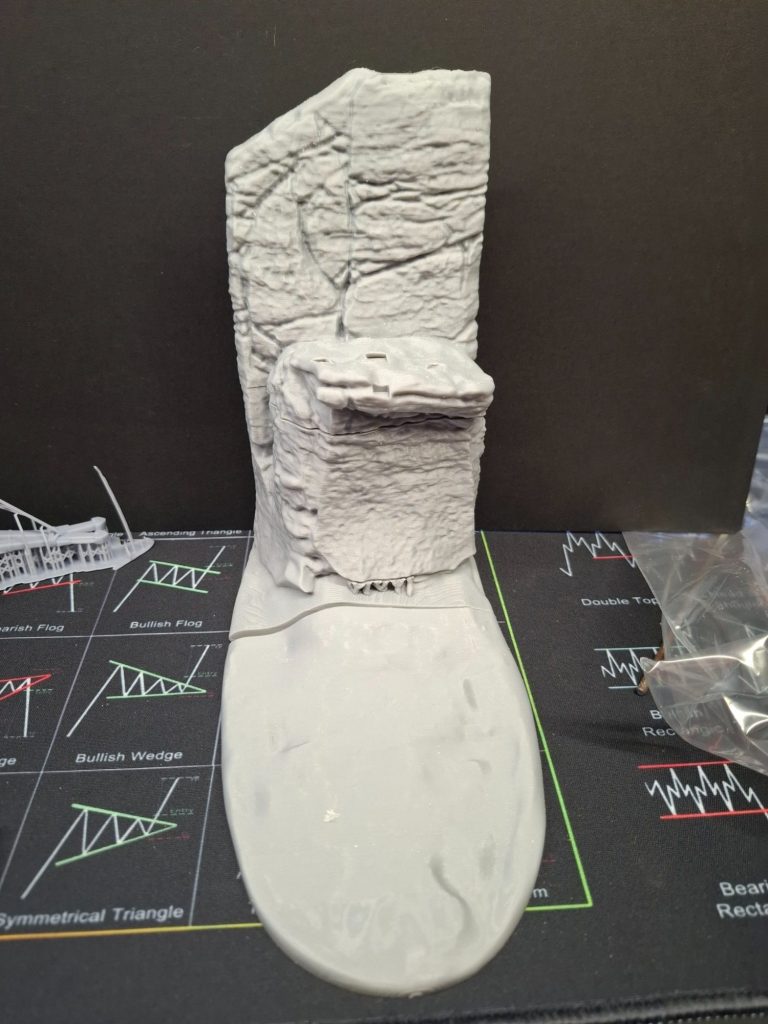
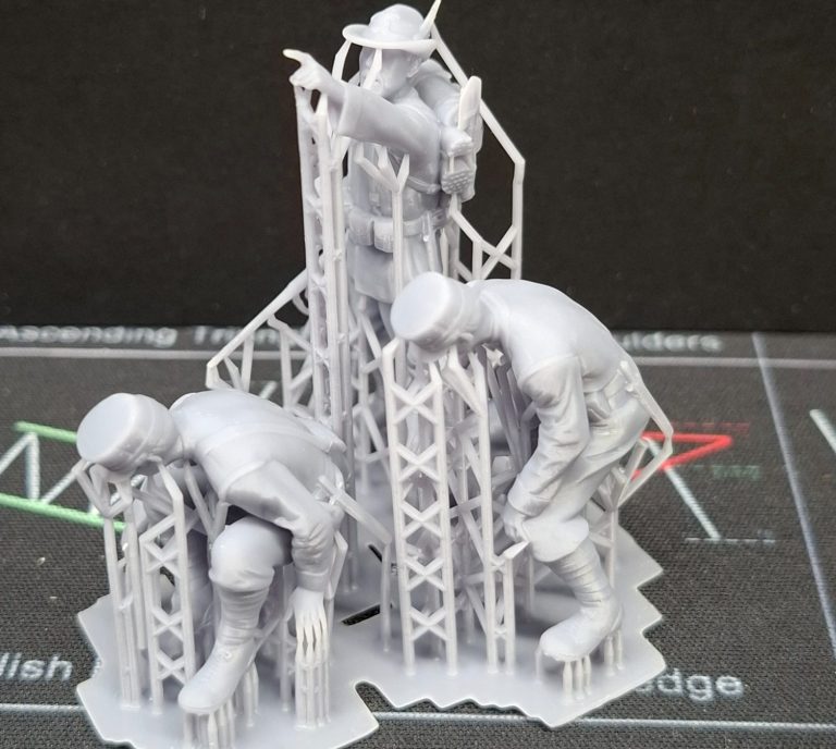
Photo #4 shows the three parts of the cliff side that come with the kit.
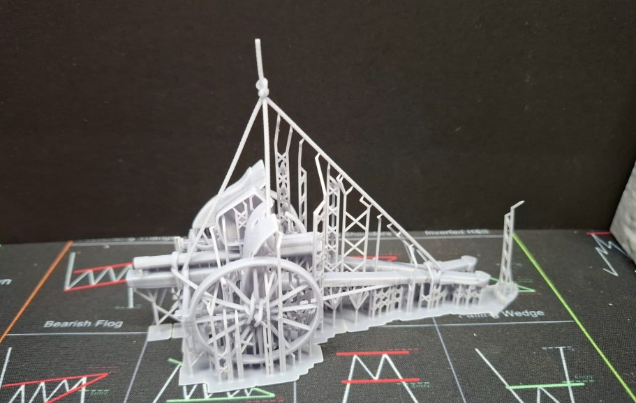
Photos #5 and #6 show the 75mm gun and the crane jib along with the officer figure. The 3D printed supports are all left in place, and this helps the very delicate parts get to the buyer in perfect condition.
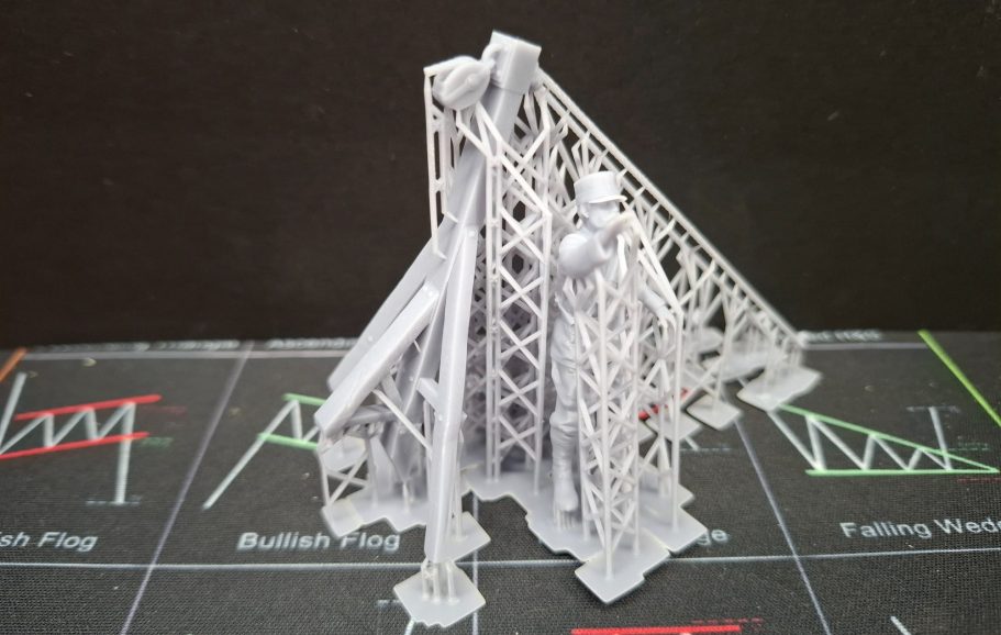
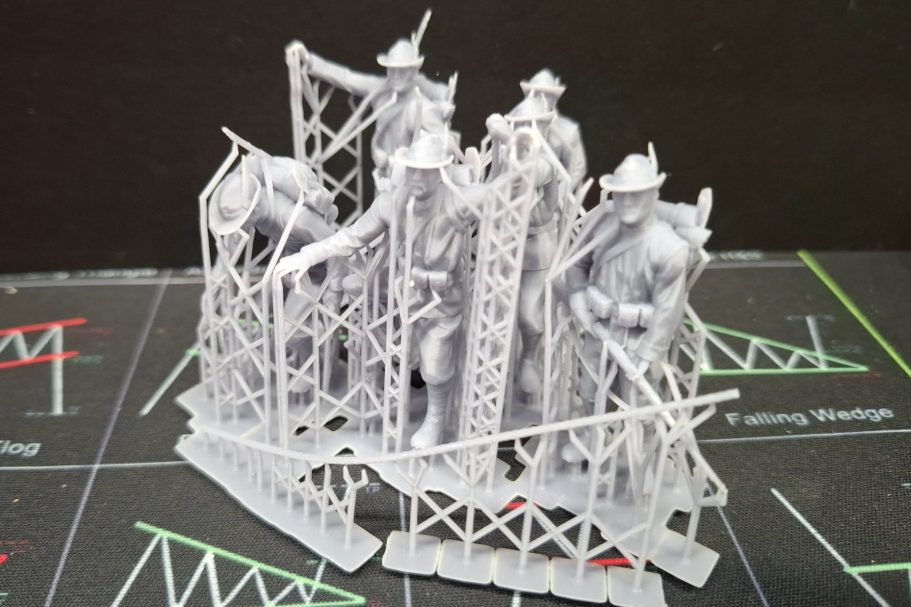
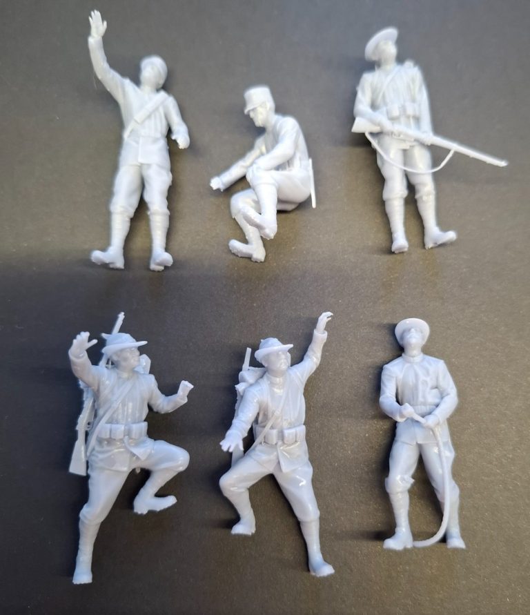
Photos #7 and #8 show the rest of the figures, again with supports from the 3D printing process still in place, and again this protects the very fine details that the figures possess.
Removing the supports is easy, but takes time. There’s no point in rushing it, as I’ve mentioned, there’s some very fine detail on the figures, gun and jib that patience will be rewarded if you take your time.
I’d advise some hot water to warm the parts and their supports up in prior to trying to remove one from the other, and a good set of fine side cutters to gently separate things.
1/35th scale, and fingers are separated / spread rather than formed into a flattened flipper with knuckles.
Ropes are thin and nicely to scale, and best of all, there were only two support part points that left a dent in the component of one figure that needed a touch of filler.
TAKE YOUR TIME is the order of the day.
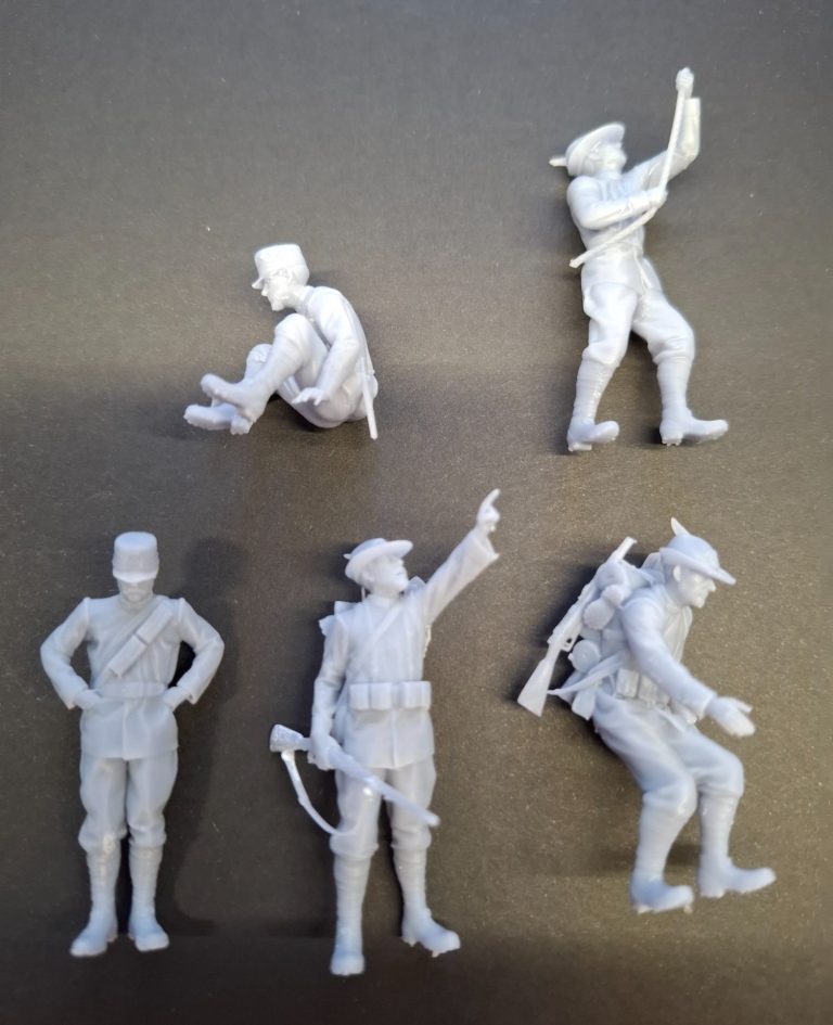
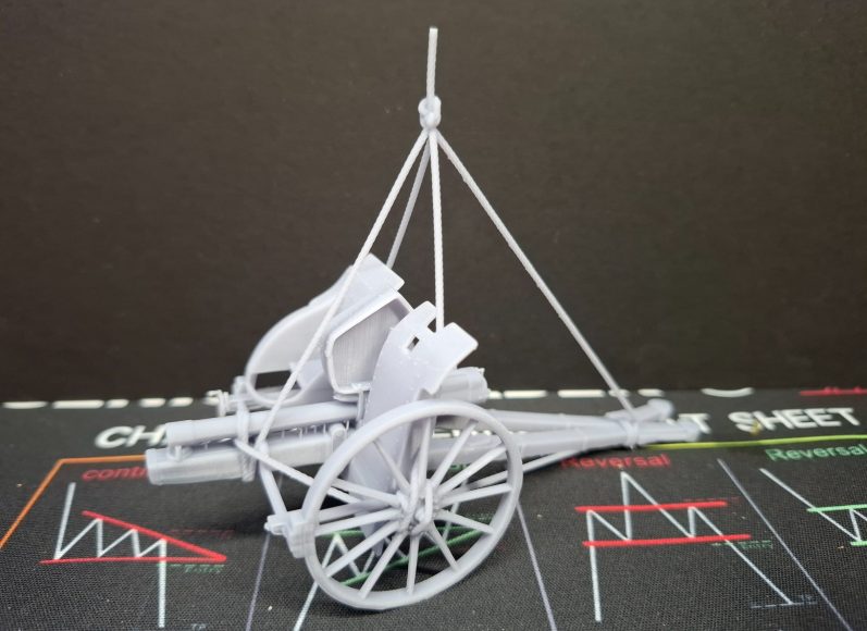
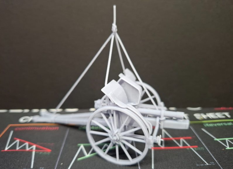
Photos #9 and #10 show the figures having been separated, and photos #11 and #12 show off the gun along with it’s rope slings for lifting it.
The components, particularly that gun with it’s lift gear are something to behold, and I can honestly say that I spent a good five or ten minutes twisting and turning the gun around to marvel at the detail and how complete and clean the “casting” was.
Amazing what one can get out as a single part from a 3D printer.
So, to make the diorama accurate.
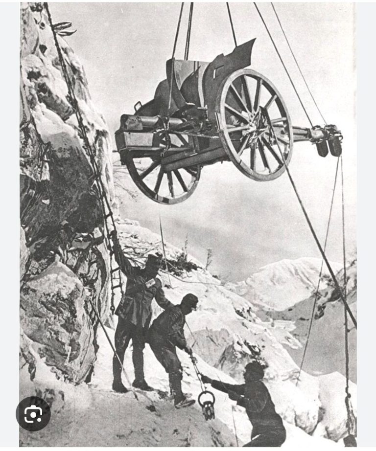
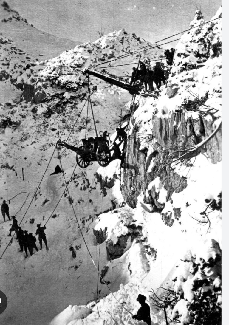
In the first few pictures I’ve shown part of the kit I constructed, giving little away really, and pictures that I downloaded showing the drawings of actual lifts done by Italian Alpine troops to move this type of gun around the mountainous areas the artillery pieces were needed in.
So what an I going to change.
- Well the cliff for a start. It needs to be a vertical section of mountain.
- The jib needs to be thicker and longer to match the one shown in the historical picture.
- The lift gear needs to have a pulley block set up with multiple reeves to offset the mass of the gun and allow fewer me to be able to lift it.
Let's start with the pulley set.
Or some calculations first.
As I mentioned, there’s several web pages that allow you to put in weights and measures for what you need to lift and using different amounts of reeves on the block and tackle will give results that are more suitable for how much mass will result for the lifters to work on.
Note that mass is measured in Newtons, not kilos, and there’s ten Newtons to a kilo.
With the three reeves on this pulley system I’m proposing to make here, the lifters will need to cope with approximately 85kg between them. So two or three chaps should be able to manage it.
Here’s the meat of the calculations:-
Moving pulley wheels = 6
Load = 10150 N
Mechanical Advantage = 12.1
Anchor Force = 10995.883 N ( The minimum force that the jib anchors would have to be able to stand to lift this amount of mass. Usually this would be doubled for reasons of safety, adverse conditions and possible “Shock loading” taking place – the latter is certainly important in this diorama’s case, because the gun, when being lowered, is going to be pushed off the edge of the upper cliff edge. Minimising any “shock” to the lift gear during that process is very important, as it could cause lift gear to fail / break or cause damage that whilst invisible to whoever checks the lift gear prior to use, might cause failure when the equipment is used again. )
Effort Force 845.833 N ( what’s needed by the fellas lifting the object )
The other thing to note is that they will have to move it six times further – if the start point is ten metres below the end point, then with this block and tackle, they’d need to pull sixty metres of rope through the pulleys because it’s not a direct lift, the distance between the pulleys shortens with each pull that the men make, and whilst the first reeve rope moves faster, it’s reduction is transferred to the second, third, fourth reeve etc.
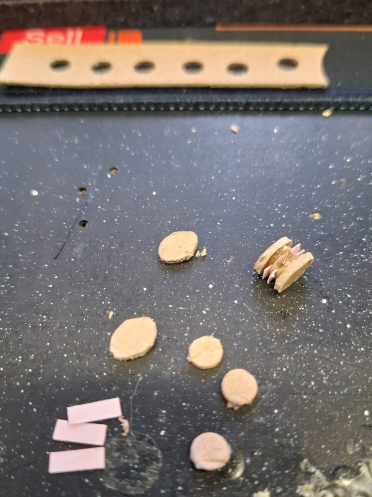
Photo #13 shows a selection of card components I thought might be used to make the pulley blocks.
One block on the right has been assembled.
The circles are produced by a hole punch used to fit paper sheets into a ring binder, the block dividers are rectangles of thin card and the block ends themselves were the most difficult to make, being carved shapes from cardboard.
Why did I used cardboard ?
Haven’t a clue, it seemed like a good idea at the time.
As it was the circles that would be the pulley wheels were discarded, as too were the dividers, and instead I used short lengths of electrical wire with the plastic sheath still on the central section of wire, and the card block ends threaded onto the bare wire.
Why discard the other bits.
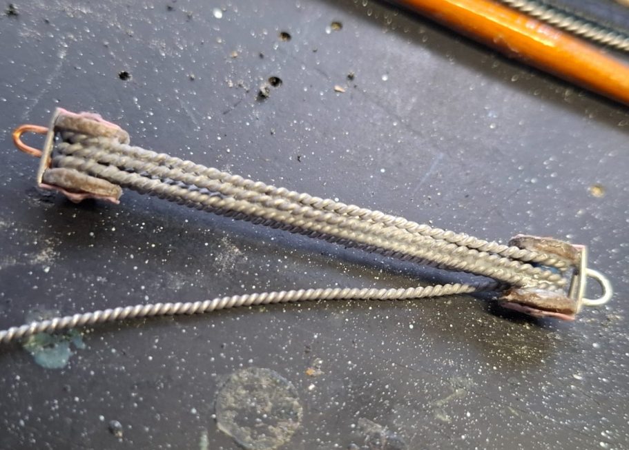
I didn’t need a working pulley set, and photo#14 shows the pulley blocks assembled and attached to the “rope” with three visible lengths between the upper and lower blocks.
The “rope” running off to the bottom is what the two men lifting the gun will be holding, and I have added hook loops to the upper and lower ends to fasten the block and tackle to the jib and gun’s lift tackle.
It looks a little rough at the moment, that’s because I used two lengths of soft wire twisted together, to make the rope and then held it in place with superglue sprayed with accelerator to set it quickly.
A gentle brushing with a toothbrush will clean this up nicely.
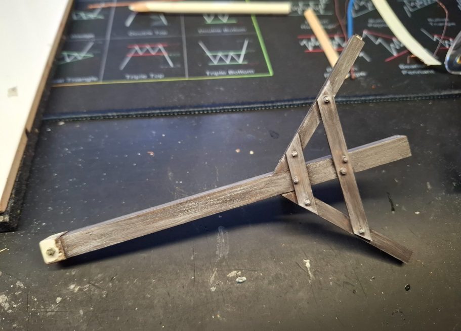
The Jib
Photo #15 shows the new, thicker jib. The length of it is probably much too long, and it will be shortened to the correct size once I begin making the diorama setting.
The jib itself is a piece of square section bass wood which is approximately the right size when compared to the thickness of the jip in the historical drawing. The end with a simple hook was made from plasticard for the reinforced metal cap and a piece of thin copper wire bent into a hook shape and fastened into a hole drilled up into the end of the jib.
At this point I was rather keen to work out how the base was going to be constructed. I’d mentioned a footprint size for the diorama would be 20cm x 20cm, but had to adjust this to something a little larger – 25cm x 25cm – because I thought that the figures, crane and gun might be too tightly packed in that space.
To force myself to keep within that space, I made a plinth from some solid White Oak worktop, sanding and polishing it to gain a nice finish along the edges, underside and top.
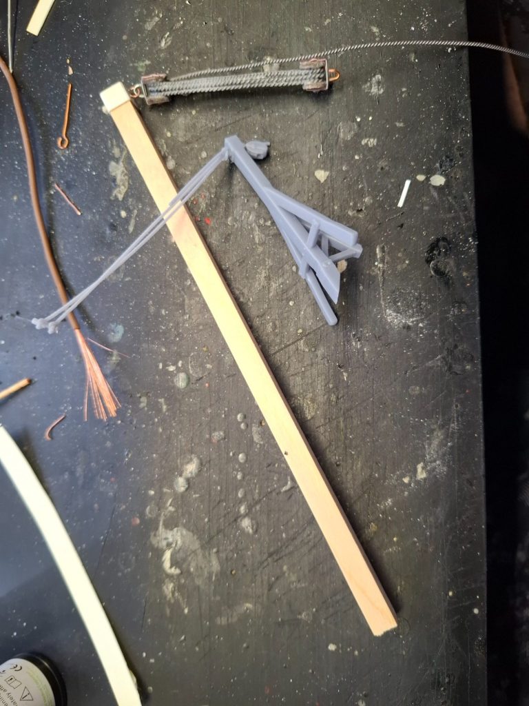
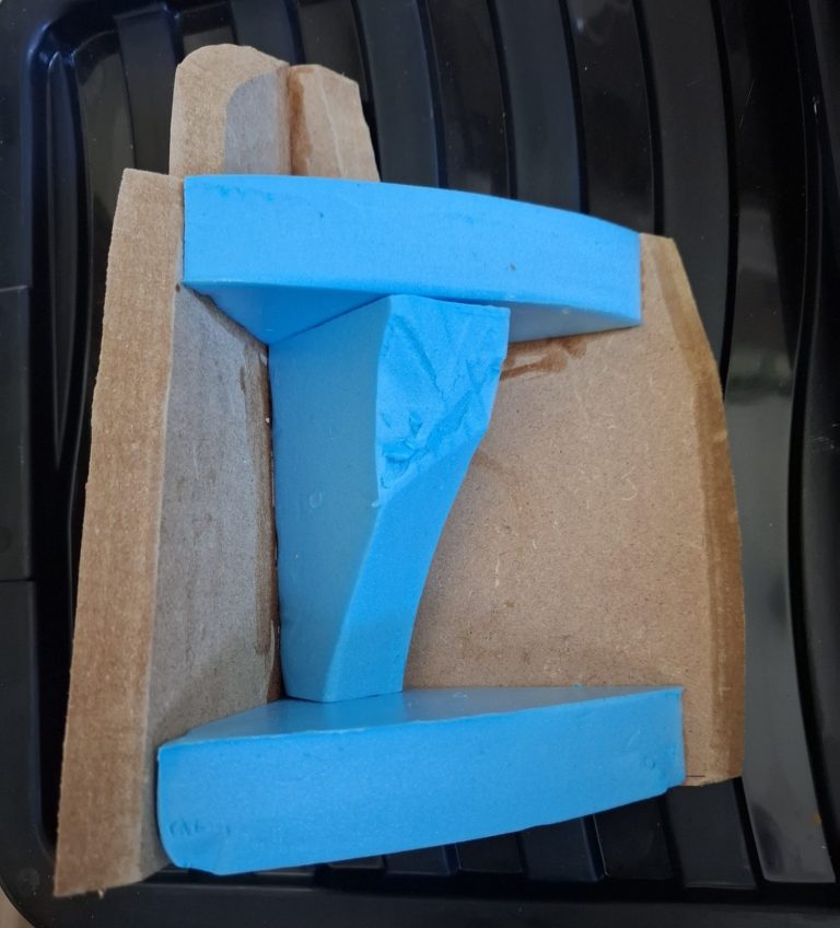
Photo #16 shows the carcase for the cliff face, which, because of the plinth I could get a fixed idea of the size and spacing for the different components.
The blue material is dense foam insulation, and the wood coloured sections are MDF cut to a rough shape.
I used a jigsaw to cut the edges of the MDF at an angle so that I could then attach the “cliff face” material to it securely without huge gaps.
Photo #17 shows the cliff section with the front covered with cork bark. This material makes for excellent rock detail, although it is a little bit too vertical as yet.
Why add the smaller section at the top / back ?
Well, I needed to replicate the support cables that help keep the crane from toppling over the edge of the cliff, and these will run from near the end of the crane jib to points secured into this smaller section of cliff face.
My thoughts ran to having the cannon being run along the raised section – so I’d need to make cart-wheel tracks in the snow there, and it would then be manoeuvred over the edge to be supported by the crane jib, the cannon being supported by guide ropes during this procedure, these ropes then being thrown over the edge of the cliff so that they could be used by men on the ground section to control any swing or spin that the gun made as it was lowered off.
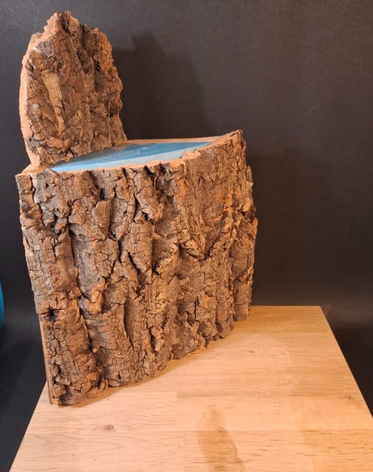
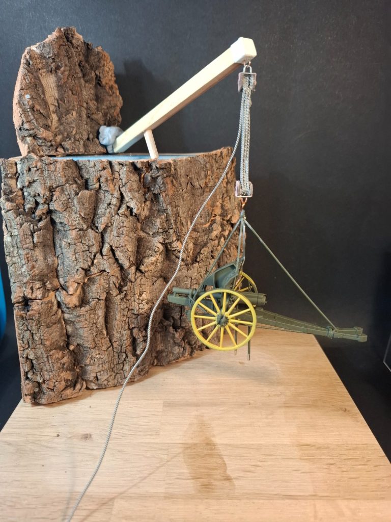
Photo #18 and just to prove that the spacing is OK I temporarily set up the jib, pulley set and gun in this shot.
There’s a deal of planning in this set-up, partly because of the replaced jib and pulley set, but also because this was going to have to be transported to Belgium to the fellow who had commissioned it.
So my plan was to have the jib and pulley set fixed in place, with the lift rope being handled by a couple of soldiers, the guide topes ( Tag Lines ) that had been cast over the edge from the upper level would be dangling from the gun still, which would simply hook onto the bottom of the pulley set once safely in a display case.
With the planning taken care of, it was time to add a little paint to things, the gun can be seen with it’s dark olive green and light wood areas undercoated in the last shot, and in photo #19 I’ve painted the crane jib with dark brown oils lightened with streaks of Buff Titanium.
The metal parts will be painted soon, maybe with some light rusting added to them.
I was praying that I could find a gun that had had some form of camouflage added to the shield, but the only examples I could find seemed to be either mid grey or a dark olive colour – camouflage, say a grey and white would have looked really cool, but let’s try and stay accurate Adrian !
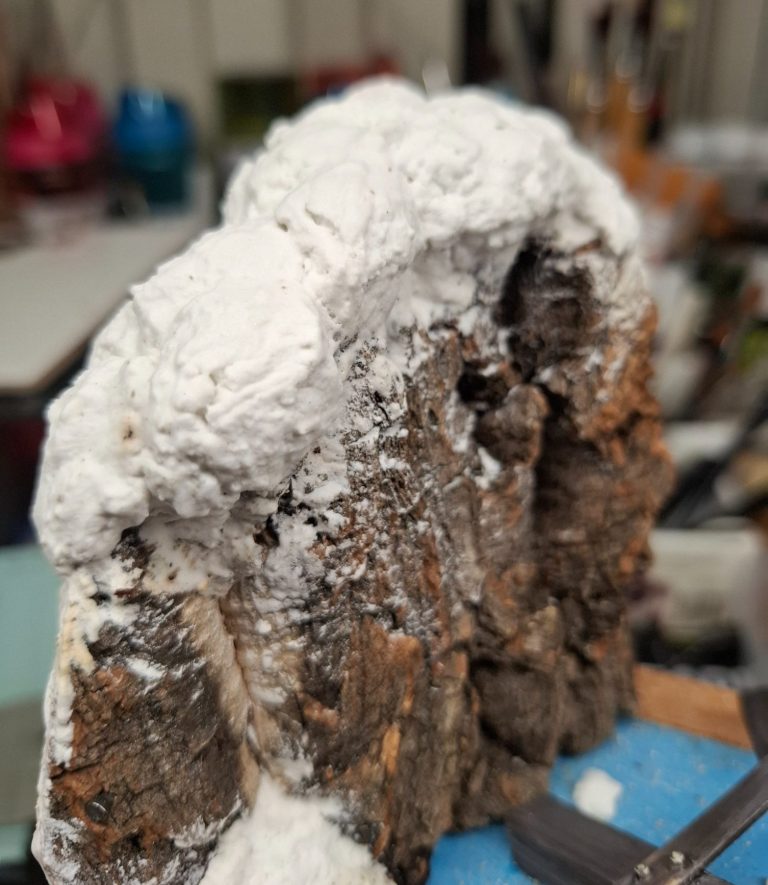
Now here I have to admit that giddiness crept in, because I had gaps to fill between the inner edges of the cork bark and the blue insulation material.
Photo #20 shows that I’d begun adding some ready mixed filler to the top of the cliff, and oh look, doesn’t that just look a little like piled up snow.
Indeed it does Adrian, and as there’s no figures going up there, why not add more to get the shape and depth that you’d need ?
Giddy indeed.
And I even added some to the lower cliff section – photo #21 – because it was looking pretty good to be honest.
I knew there needed to be figures and other details added here, so I didn’t go right across this section of the cliff, but I did temporarily fasten one of the support arms of the crane into the snow.
Why has giddiness got the better of me ?
Well I haven’t painted the bleedin’ cliff face yet, have I !
Which will entail colour of some kind getting onto that nice, pristine white snow.
Bugger !
So that was sorted next, with a quick check on what colour the rocks are in the Italian Alps.
Good job I looked that up too, the rock, particularly in certain lighting conditions has a distinctly “pinkish” glow to it. Apparently it ain’t grey, and I suspect that even in poorer winter lighting conditions, it tends towards browner hues.
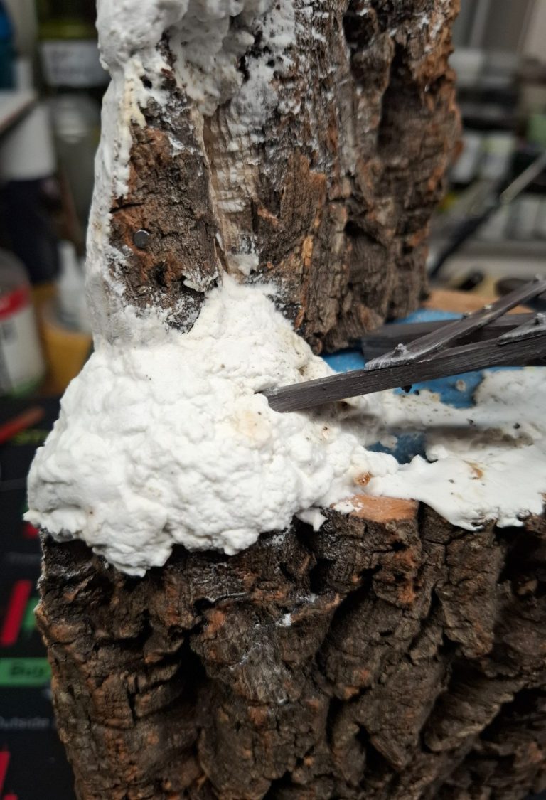
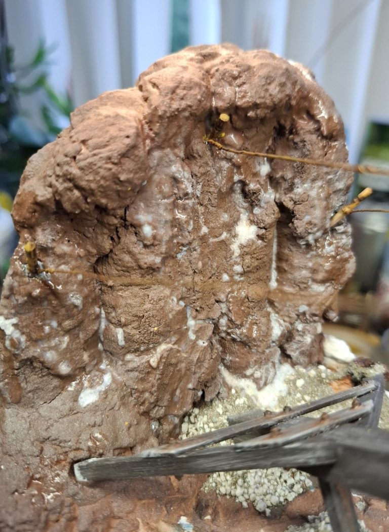
Photo #22. So, Grey Primer to begin with, followed by Army Painter Brown primer, a squirt of “Red Lead” primer, a dusting of White Primer, and leave to dry.
Remember, this is going to have all the higher / raised detail covered in a dusting of snow, so really I only needed to apply paint that would be, at best, mid-tones, or more likely in shadow.
Whilst this dried, and before I could add anything to the groundwork, I needed to get the figures painted.