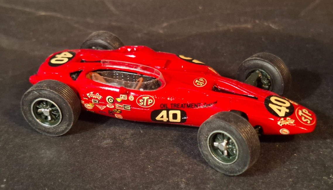
STP Paxton Turbine
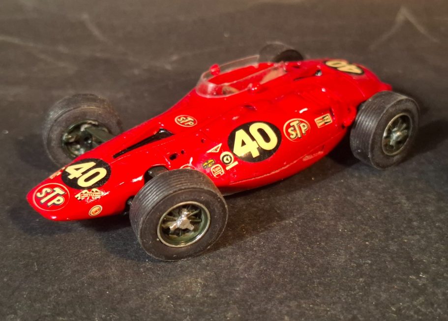
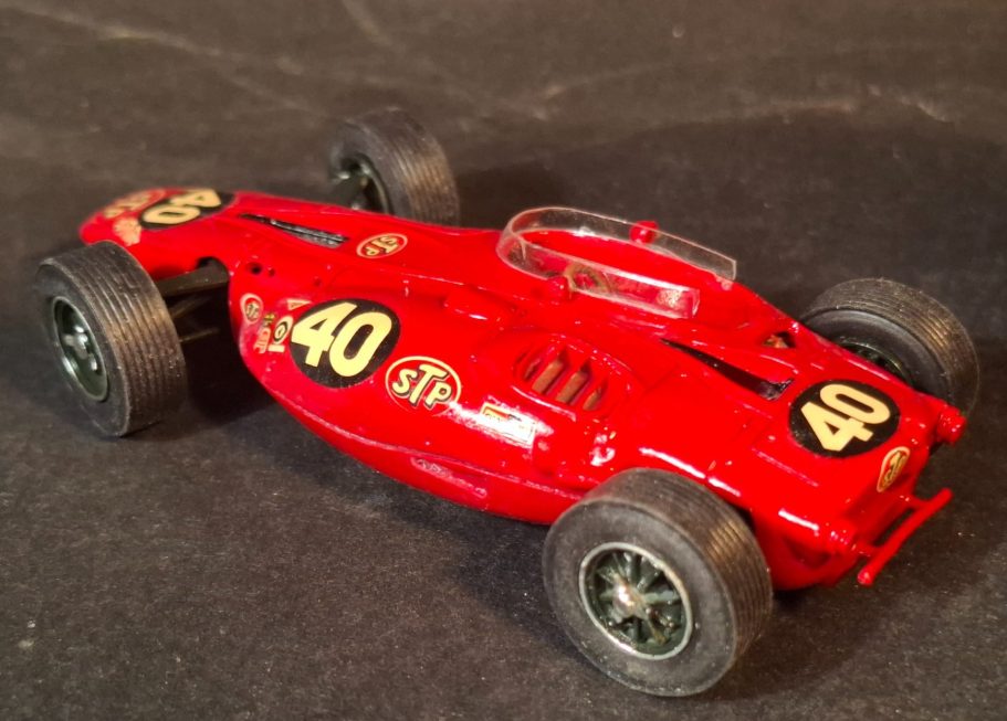
1/43rd scale white metal kit from SMTS
Assembled and painted in 2026
History
Althoughit looks like some science fiction beast of a car, the STP Paxton Turbine was an innovative design from Ken Wallis, an American distantly related to Barnes Wallis ( the British engineer who amongst other things designed the Bouncing Bomb used during the Second World War).
The design of this car was to be used for the Indianapolis 500 in 1966, although Wallis had problems getting support for his idea of coupling a gas turbine to the drive train of a wheeled vehicle.
His approach initially to Dan Gurney ( engineer and heavily involved with Formula 1 motor sport ) was turned away, and Wallis then sought favour with Carroll Shelby.
Shelby thought the idea to be unworkable, and is thought to have called the notion “hogwash”.- remember that one, because I’ll return to Shelby’s dismissive comment later.
Not put off by these rejections, Wallis found support from Andy Granatelli at STP and Wallis and his team moved to Santa Monica to develop and build the car in January of 1966.
The engine was a Pratt and Whitney Canada ST6B-62 turbine engine, used primarily as an aircraft engine in turbo-prop frames, and also for helicopters. In such usage, the engine has been extremely successful for many, many years, although continued development updating the initial designs have of course been made.
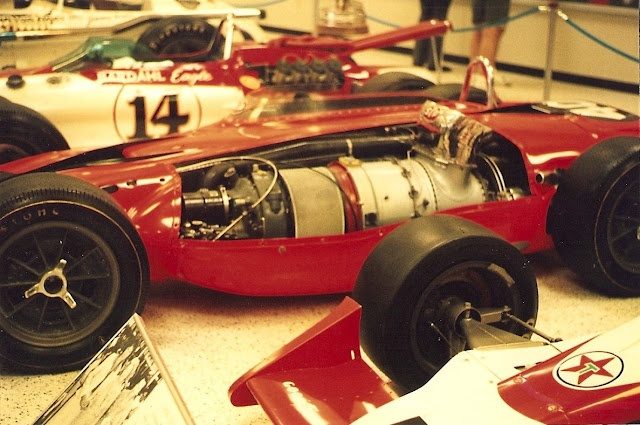
Photo #1. Mounting such a gas turbine into a racing frame wasn’t going to be easy, it’s a large engine that takes up a lot of room, and Wallis’s designs called for it to be positioned alongside the driver – an offset, mid-engined car, if you will.
Initial thoughts had been to have the driver in an offset gondola – imagine something similar to a motorcycle and side car arrangement, and although a similar design had been used several years by Smokey Yunick, the idea was passed over and the body shape shown here was used instead.
Unusually for the time, the car sported a four-wheel drive layout, as opposed to other cars being rear wheel drive.
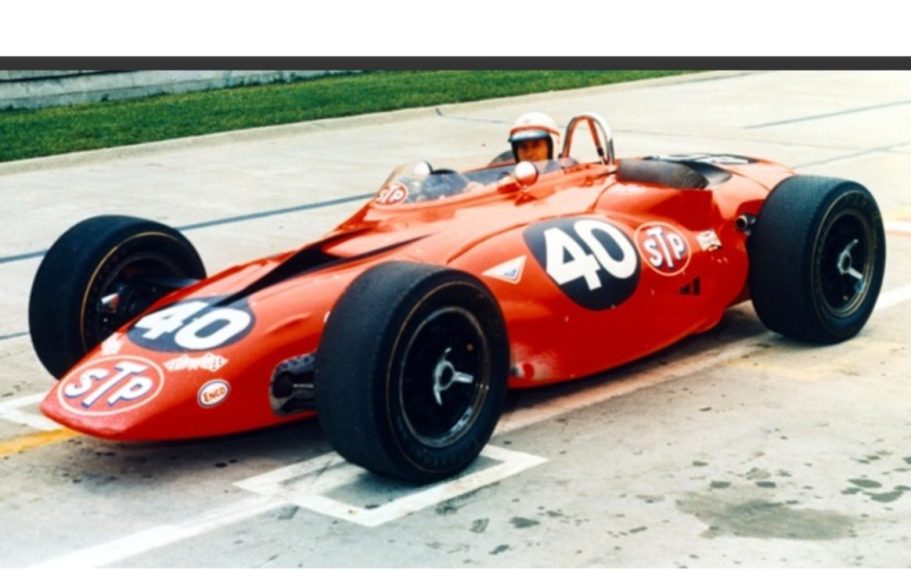
Unfortunately, the heat treatment given to the aluminium frame of the car badly warped it, and the deadline for the Indianapolis 500 in 1966 was missed. But the car was ready for the 1967 race, driven by Parnelli Jones.
Photo #2 shows a picture of the real car, and to be honest, it was this shape that caught my eye and made me want to build the kit.
The car did really well, leading the race from the start, and for most of the time after that until with only eight miles left, there were transmission bearing problems and the car rolled into the pits, unable to complete the race.
It must have been devastating for the STP team, to have produced such a superb design, with such forward thinking engineering, only to fail so very close to the winning post.
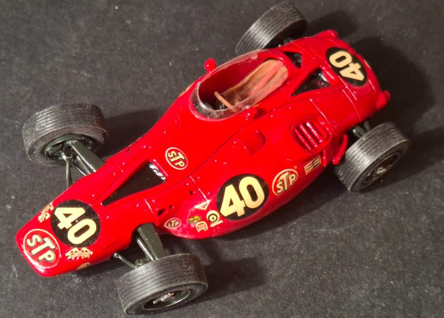
The car was entered again for the Indianapolis 500 in 1968, this time driven by Joe Leonard, but crashed catastrophically during practice and was unable to be rebuilt. It never raced again.
The car was donated to the Smithsonian Institute, and an exact replica was also produced, using original plans for a display at the Indianapolis Motor Speedway Hall of Fame.
The Lotus 56 used a similar engine in four cars soon after, one crashed on the first turn, killing it’s driver – Mike Spence – and the other three didn’t finish the race.
The governing body – USAC – subsequently banned the use of gas turbines within racing, and included within that ban the use of four wheel drive cars.
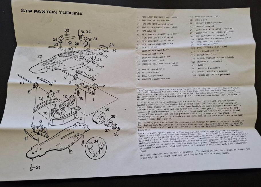
The model.
As with a lot of models of cars, AFV’s and aircraft, I manage to source them second hand, and this kit was no exception. It’s a scale I enjoy working in, although some kits can be very simple – the ones from Starter Models usually fall into this class – whereas Tomeo and Marsh Models tend to be more complex.
This kit from SMTS sort of sits in the middle, with plenty of white metal parts, which assemble fairly easily…… if your superglue decides to work – more of that later.
Photo #3 shows the instruction sheet in full, with an exploded view of the parts along with a written description of how they should go together.
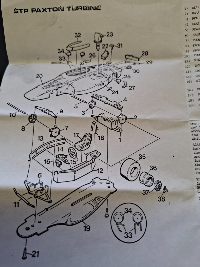
Photo #4 shows a close-up of the diagram, and although it’s pretty obvious where most parts should go, there are one or two whose exact location needs referring back to the pictures of the actual vehicle.
Photo #5 shows the underpan of the model with the forward and rear suspension components. At this point I may as well say that all the kit parts are well moulded, very few part lines and although there is flash on the smaller bits, it’s easily removed so the modeller can get on with assembly.
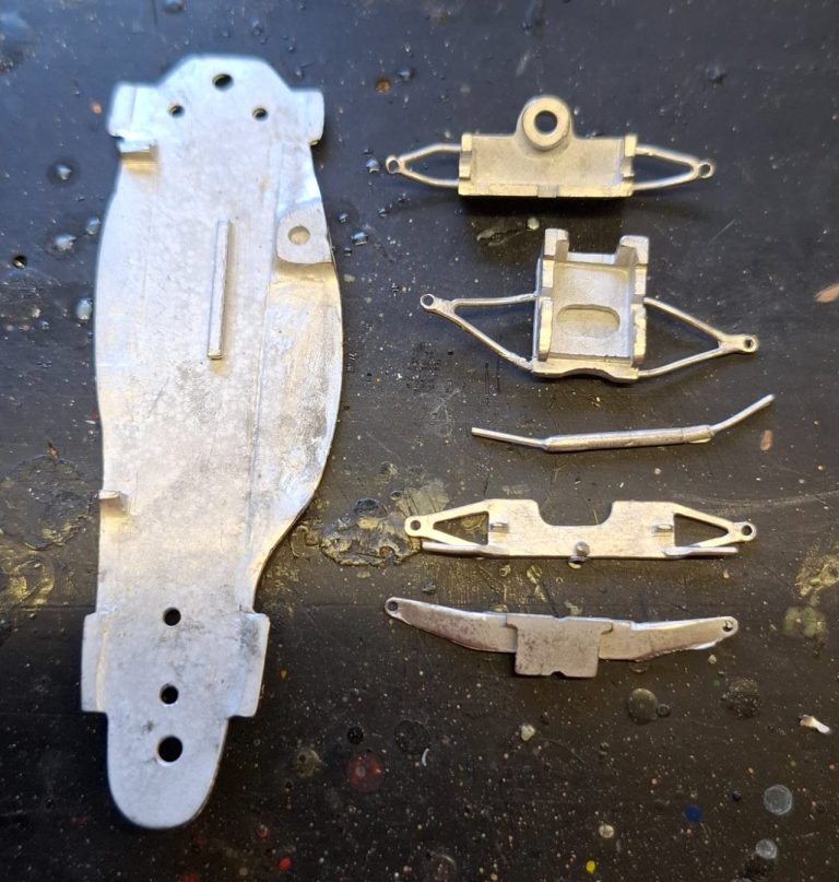
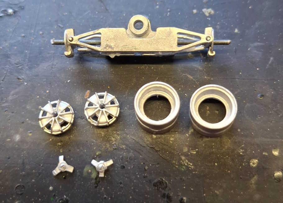
Photo #6 shows the rear suspension assembled, there is a single long wire included in the kit to make the drive shafts for the car, this has to be cut to size before installation.
I’ve got to admit that the construction of the front and rear suspension was a lot easier than it looked, the wire pin slotting through the brake discs and main block effortlessly although I did trim off most of the wire drive shaft to allow the wheels to be fitted.
Photo #7. Although most car modellers seem to like their cars with the front wheels in the central position, I like mine to be steering to one side, does it make it more interesting ? Possibly, but I just think it makes the car look like it might be used,
In this shot, note the turbine exhaust sticking up at the mid to bottom left. It’s attached to the base plate by as little spigot, and to be honest fouled the sit of the body when I tried test fitting the two parts together…..
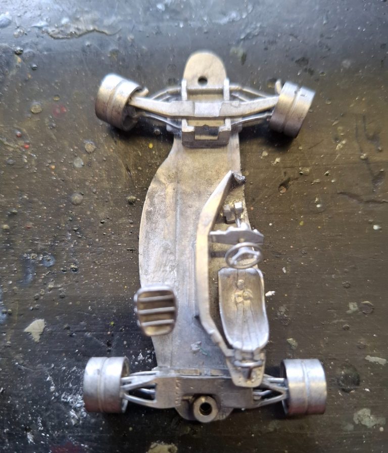
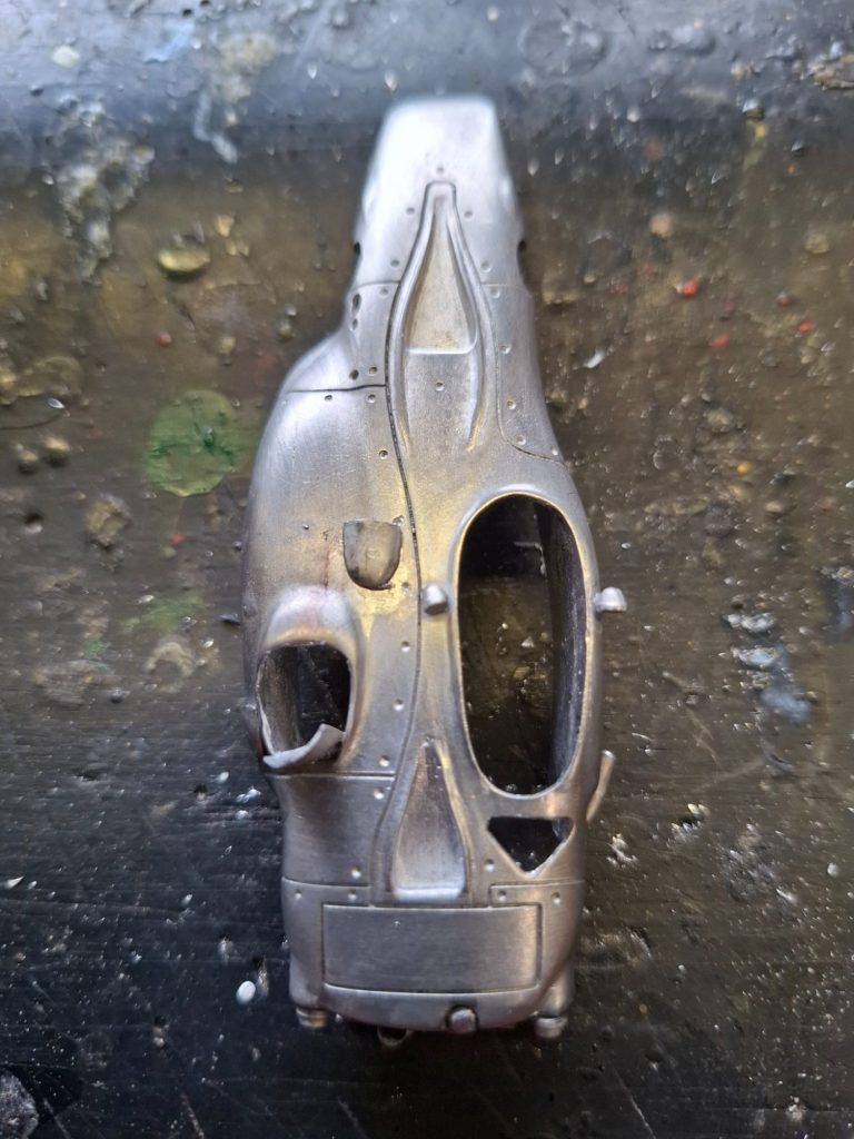
Photo #8. Shows the upper body, there’s a small part line runs around the lower edge of the body which needs cleaning up, and all wheel arches have flash that needs sorting out, but the metal is relatively soft, and it doesn’t take long to get all that done.
There’s a heat guard on the exhaust outlet shown here, it seems much too large to me, and I removed it completely, replacing it with a small piece of foil later on.
Photo #9. There is a problem with the exhaust itself.
It comes up to protrude from the body, and is attached to the underpan of the car by a long spigot to hold it in position.
Having fixed it in place, I then test fitted the body and found that it’s nigh on impossible to join the body to the underpan with the exhaust in place.
Solving that exhaust problem, I removed the spigot that is on the underside of the exhaust, and used some Magic Sculpt putty to secure the part in place as shown here.
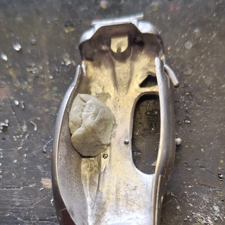
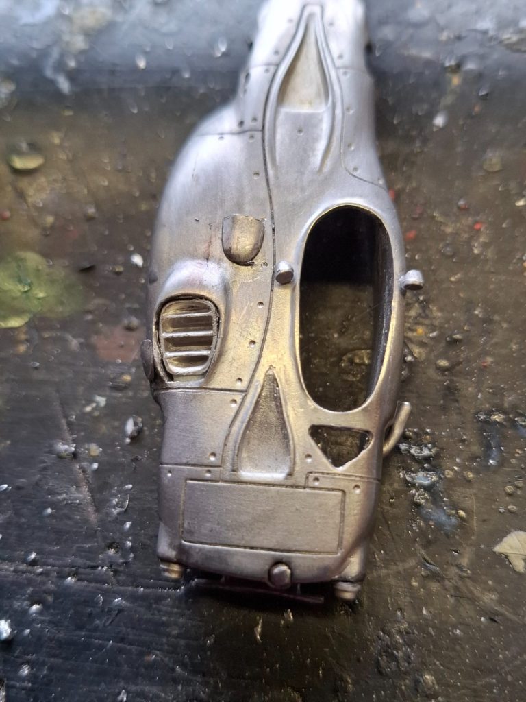
Photo #10, and this shows the exhaust in place, allowing me to fit the body shell onto the lower section without any problems.
Photo #11, see, all put together to test fit the subassemblies.
I mentioned earlier about superglue “working” or in this case not working. I had a lot of problem with the glue just not holding things in place. Whether this was because of the hot summer somehow denaturing the glue, or maybe I’d got some old stuff that had gone off somehow – I tried a completely new bottle of the brand I use regularly, and this too seemed to temporarily fasten parts in place, only to have them detach later on, The small three pronged hear guard was a particular perpetrator of this, and being so diminutive, was downright frustrating in it’s resistance to stay put.
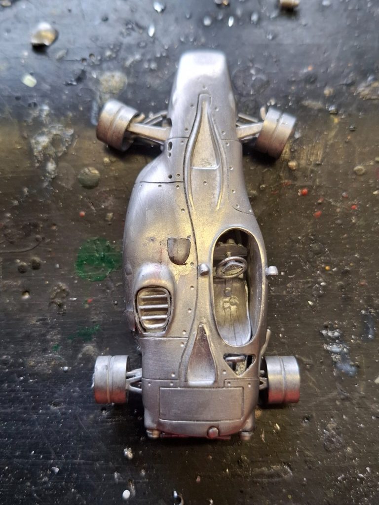
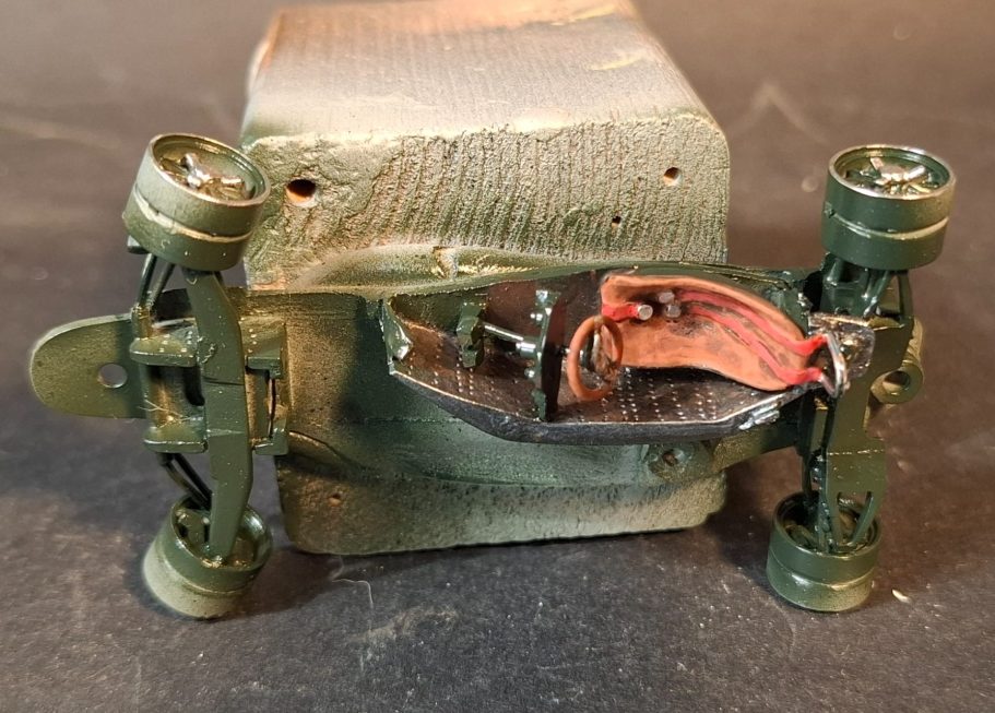
Photo #12. The finished lower part of the car, which does look like a stripped down go-cart at the moment, and just needs the tyres fitting.
The seat has been painted to represent a leather covering, with the seat belts matching the red of the car’s livery.
The steering wheel wasn’t quite fully formed, so I had to do a little remedial work on one side of it with some small spots of superglue and activator, building up the missing area.
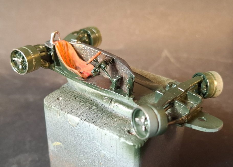
Photo #13, another view of the model at this stage.
Unusually, there isn’t a decal to give you the dials on the dashboard. Fortunately I had a spare set in the box of bits and bobs that I keep from previous kits, and this, whilst only giving a couple of dials, is enough to make the small section look OK.
The “bucket” of the cockpit was painted in Darkstar Metallic acrylics – Dark Steel and then just a little bit of silver, and the head restraint was topped off with a little bit of Molotow Liquid Chrome.
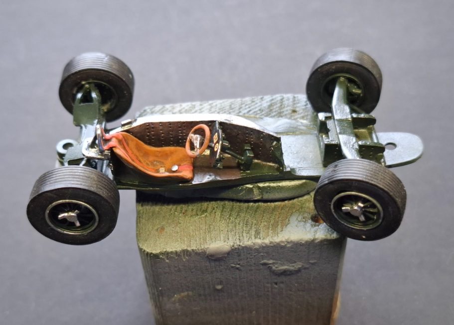
Photo #14. The reason I’d left the tyres off was to enable me to paint the thin line of silver around the rim of each wheel. The star shaped wheel nuts are painted with silver too. One thing that I hadn’t thought too much about was the rigidity of the tyres.
They’re really, really hard rubber, possibly not helped by the age of the kit, but even soaking them in boiling water for a few minutes, didn’t soften them to any great degree, and so getting them onto the wheel hubs was a test of using gentle brute force.
Not gentle enough, and perhaps a little too much brute force, as I broke the front right wheel hum away from it’s mounting.
A simple job to glue it on, but still a little frustrating.
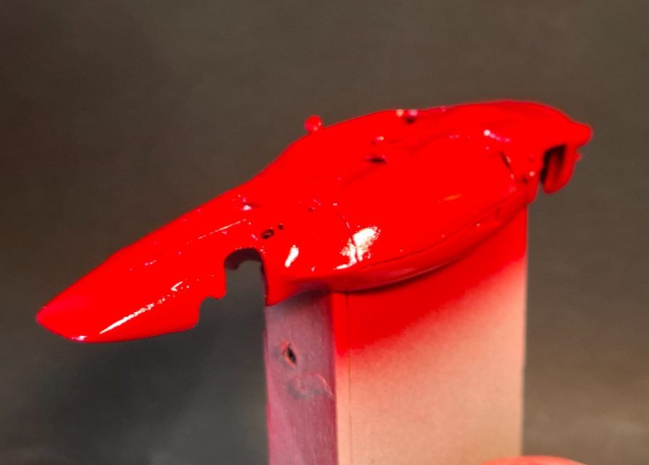
Photo #15 and I began painting the bodyshell. I gave it a good wash for the component first, and allowing it to dry in the drying cabinet overnight.
Whilst it was still warm, I dusted on a couple of thin coats of grey primer, then followed that with white primer sprayed on from above so that the grey would provide “instant” shadows when the red paint was applied.
Here the first two coats of Tamiya Red had been laid on, and after each coat of either primer of in this case the red, the bodyshell was put back in the drying cabinet for a couple of hours.
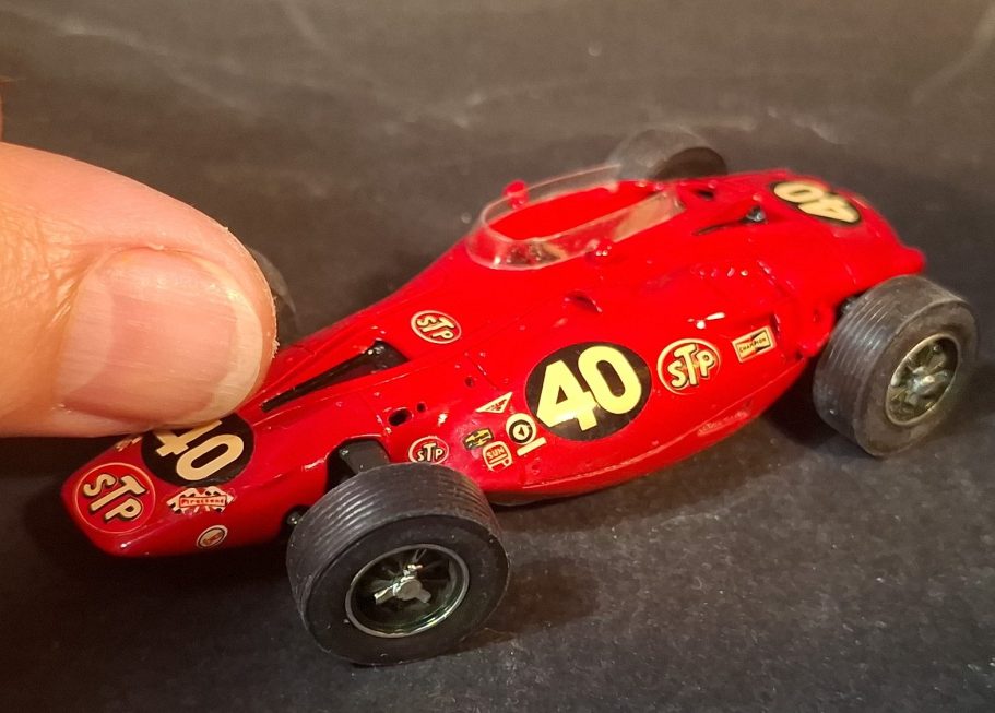
Photo #16 – Decals and a thumb.
So, the thumb is to show just how small this scale of vehicle model is, and the decals are really nice and thin. There isn’t any guide to where they actually go, and I couldn’t find any pictures of the real car taken from the right hand side.
however, the side decals are different, and the one saying “Oil Treatment Special” needs to be on the right hand side of the car.
To be honest, once that’s been decided, then it’s plain sailing. The decals go on easily, but do slide them off the backing paper onto the surface of the vehicle as they curl very easily if you try lifting them off with a brush, and getting them to flatten out after that will place you in the land of gritted teeth and certain curses.
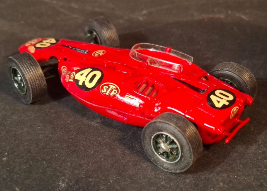
There’s some very thin black trim lines to go around the front and rear vents. After trying to get one of these in place I abandoned that idea and decided that painting them on once the model was fastened to a bit of groundwork would be much easier.
The wind shield is relatively easy to cut out, although sharp scissors are a necessity, and I fastened this in place with some wood glue, using some small blobs of plasticine to hold it in position until the glue had cured.
Before adding the bodyshell to the underpan, I gave it a couple of thin coats of Mr
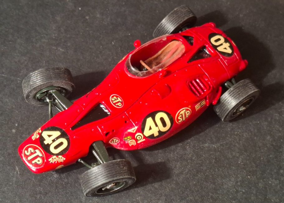
Hobby Gloss Varnish to level off any decal film edges and protect the paintwork.
All that was left to do was to drill a small hole underneath to accept a screw to fasten the car onto it’s plinth, paint in those black trim lines and also paint the turbine exhaust black.
There’s also a couple of air scoops that needed painting black I think – the ones on the side of the body, just in front of the rear wheel, but I need to check references before I do that.
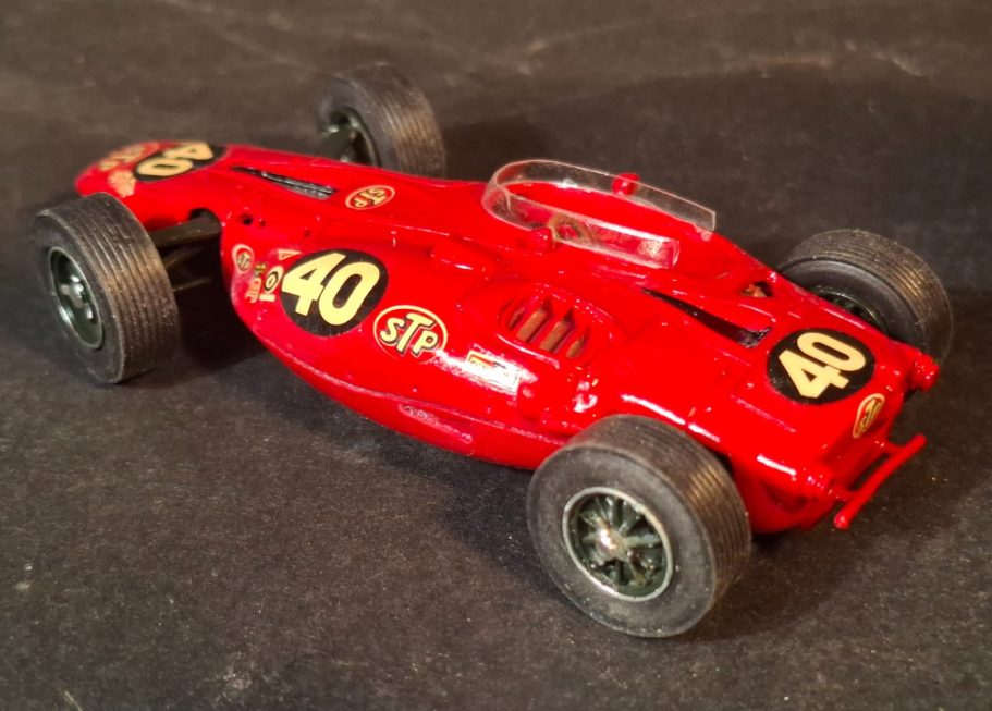
Final thoughts.
A beautiful looking racing car, that is a rare kit to find. There is ( at the time of writing ) a 1/24th scale plastic kit on eBay, but the asking price of £720 is a little bit rich for me even if it does have the complete turbine engine capable of being displayed. I like the design and look of the car, and it’s certainly a landmark in racing, but I’m not that much in love with it.
This kit, can still be found now and then, but expect to pay around the £80 - £100 for it. As I say, I was lucky and found it in an auction, and didn’t have to pay that much.
Construction is relatively easy, although the suspension arms are quite delicate.
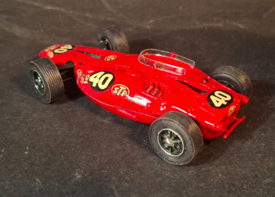
Casting is great compared to some kits of this period, there is a small mould part line around the lower body, but it is really easy to clean off and the metal is very soft, so the wheel arches are easily separated from any flash too.
There’s not much else to say, a shame though about it’s first and only race, it must have been more than maddening to have the car break down a mere eight miles from the chequered flag, especially after the design idea was rejected by others.